Landforms created through Topological Analysis of Shapes – Example 4.7
I wasn’t sure where to put this example exactly, since it came as a follow up to Example 8.4, but the general scripting is less complex so I decided to put it a bit earlier. The general problem and solution has many applications beyond topography as well, but for landscape architects, maybe its most ready application would be in the creation of landforms. It could also be used to generate generalized roof profiles for buildings in some cases.
If you already looked at Example 8.4, the recursive offsetting of base curves to create a topography, you may have tried a similar process going inward. Offsetting towards the exterior sometimes, but rarely causes problems with changes in topology, a mathematical term describing the form of a shape, but offsetting towards the inside is often a very different matter. If you are offsetting contour lines for a landform, for example, which is somewhat irregular in form, you will probably get to a point eventually where the landform “splits” into separate contour lines, or separate “peaks”. If you have an automated process in grasshopper, similar to Example 8.4 for example, going towards the inside, this can create problems.
Fortunately, there is a fairly simple solution for describing the topology of a shape through what is called the “medial axis,” and using this description in turn to create a landform out of any arbitrary closed shape or closed set of shapes. The logic of this script using Voronoi cells to find the “medial axis” is explained on the Space Symmetry Syntax blog by Daniel Piker, but here the definition is reworked to work with the latest versions of grasshopper, and also extended a bit at the end. This definition is designed to work with any number of input curves, but you will have to pay attention to the data structure, particularly the “Grafted” elements throughout for it to work properly.
Step One – Use Voronoi Cells to describe typology of shape
The script starts here with three arbitrary curves, in this case boomerangs. These curves are divided into a regular number of points, and these division points in turn are used to create a Voronoi diagram. If you look at the diagram, the boundary between the cells corresponds closely to the elements that can be described as the “Ridge” and “Hips” of our landform. You will have to increase the number of curve division points to make this line increasingly more precise, while not overwhelming your computer. Finally, we use the “Trim Region” command to trim the Voronoi cells, and we will only go forward with the pieces of geometry that are inside our region curves.
Step Two – Extract Medial Axis and “Veins” from Voronoi cells
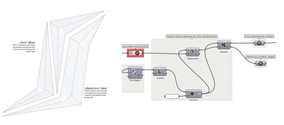
Once we have the cells inside our shapes, we can explode the cells. We now divide the remaining geometry into two classes. The pieces of geometry which touch the edge curve always run perpendicular to the slope of our landforms, and we will call these “veins” (like veins on a leaf) going forward. The pieces which do not touch the edges comprise the topological skeleton of our shape. To separate these, we will use the “Collision One” component to return a true/False value for our shapes to see if they touch the outside edge curve. These two sets of Geometry are then dispatched.
Notice also what I did with the data structure. I used the “Trim Tree” component to remove all levels of data structure except for the last one. This is because I don’t care what cell the lines used to be associated with, but I still do care which of the three starting lines each line is associated with. If I flatten all the way, it will not work properly.
Step Three – Move Topological skeleton vertically to define landform
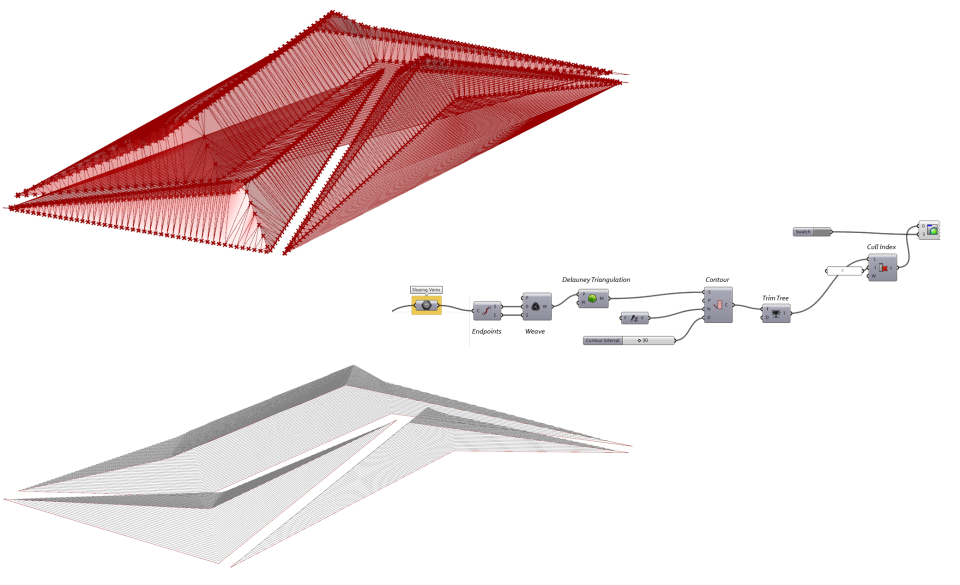
In the next steps, I will use the geometry I generated to develop a landform and a mesh. I can use either the medial axis to define this mesh, or I could use the veins. In the image above, I use the veins. In the image below, I use the Medial Axis.
 The general principle in both is the same. The endpoints of each piece of geometry are extracted, and then moved vertically based on their distance from the edge curve. The amount of movement is scalable based on the desired overall slope. Once these points are moved, the lines can be redrawn.
Step Four – Create Mesh and Contour Lines
Here I am using the endpoints of each of the “veins” to define a mesh, from which I will derive contour lines.
Step Five – Optional Lofts for the Veins
 You could also draw some geometry with the veins, but this is a totally optional step.
Variations
This definition should* work with any number of closed shapes of any size and form. You will only need to adjust the number of initial curve divisions to get results that are more or less precise. You can also adjust the height scaling factor to get various landform slopes. Below are just two examples of possiblities, based on a complex, curvilinear form, and one based on simpler triangular shapes. Note it works well in both cases!


Hi – thanks very much for this – is great – i don’t suppose you know how to adjust the script to allow for curves within curves – say a doughnut shape for example
LikeLike
Hi! Thank you for sharing with us many good “lessons”. But in this lesson, I just do as your images say, but I’ve found that the medial axis and veins are doubled lines ( as the image says), so I dispatch them,using “dispatch” (there isn’t a dispatch in your image), then I go forward to step three. Here I get the problem – I use a “polyline” to link every point, then I find I get one closed loop, not like the image say. I can’t upload pictures, can you get the meaning…
LikeLike
thanks for your comment! in response to your questions, no, I did not dispatch the overlapping lines since I think the script as I set it up needs both sets of lines to work properly. Also I use the Line component (no Polylines)
In the first version of step 3 the extra lines end up getting dispatched at the end of step3, but your version may be simpler, in which case you would not need the dispatch at the end of the step
In the second version of step 3, I need both sets of lines (I think!) to create the medial axis. I did notice an error in my image though, you input the products of the “B” Dispatch from Step 2 to draw the medial Axis lines in Step 3B, not the “Veins”. I will fix the image.
LikeLike
your tutorials are extremely useful, thanks a lot for taking the time to put them out there
LikeLiked by 1 person
Hi! How do you get the faces (on the last step) to connect? meaning how do you change from ‘voronoi connection to a regular pattern? Thanks!!!
LikeLike
You don’t connect the faces in the last step here! if you want a single mesh, that is done in the next to the last step.
LikeLike
Hi!, In step three, where are those Original Curves coming from? I don’t see the continuation from step 2
LikeLike
The curves in step three are simply referencing the original Input curves (with a wireless WiFI connection) I usually use the color yellow with a tag to indicate previously designated objects or values.
LikeLike
The Veins method was a success, but I couldn’t seem to figure out the second one. Can you please check it out?
https://drive.google.com/open?id=0B4xKuVNy7IyYel9aR3pCQ3pFclE
LikeLike
Hi thank you so much for this awesome approach to generating landforms! I have a quick question though, in the part of the script where you decide the steepness of the landform, I dont understand what the number you are multiplying it by represents, the “multiply distance by shape factor” part. Could you please clarify this? Thank you so much once again.
LikeLike
This is the Proportion of the rise to the run. If you multiply by 1, it will be a 1:1 slope. By 2 it will be very steep, with the rise twice the run, etc.
LikeLike
Thank you! I understand now
LikeLike