Example 7.4 – Kármán Vortex Street – Spiral Forces
A last major category of forces you can use in the Grasshopper Vector Field Tools are spiral / vortex forces. There isn’t a special component for these, but they are created by simply combining and merging fields for point charges together with a spin force. The result is a vortex.
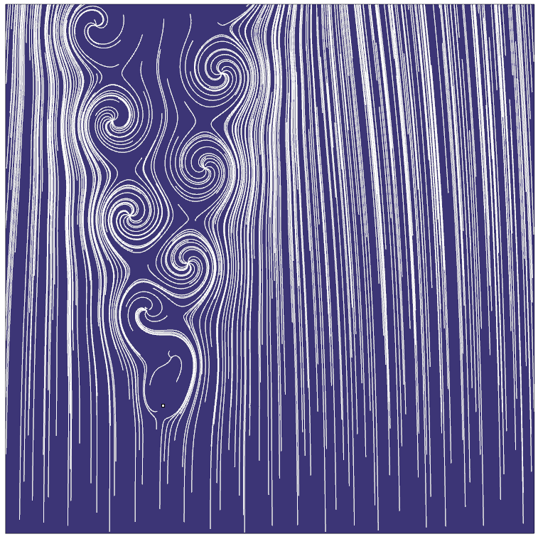
This is fairly easy to set up, but for this example I decided to do something a bit more complicated and to simulate a natural, fluid dynamic phenomenon known as the Kármán Vortex Street. This is a form of turbulence that can occur at a variety of scales from the small to the very large. They form when a certain resonance is formed by the interaction of a blunt object with a fluid system. Again, the math is fairly complex, and this exercise doesn’t purport to be a scientific model of the fluid behavior, just a reasonable simulation.
Step One – Initial Setup
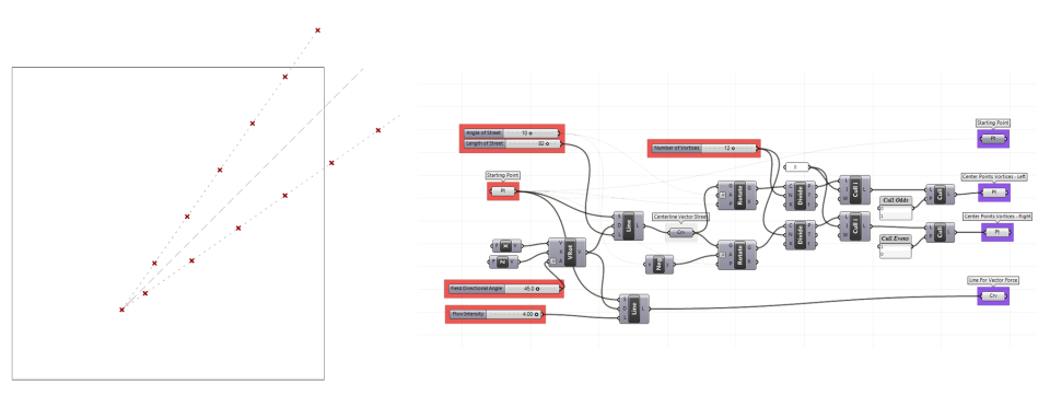
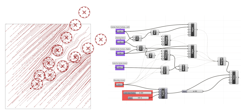
I won’t explain this in detail since there is really nothing new here, but i set up a system to generate two alternating sets of points, which will become the center points of my vortices, in the wake of a “start point”. The purple containers at the end represent the geometry I will take to the next step. Note there are quite a few parameters marked in red that I can change later on.
Step Two – Point Charges and Vector Force
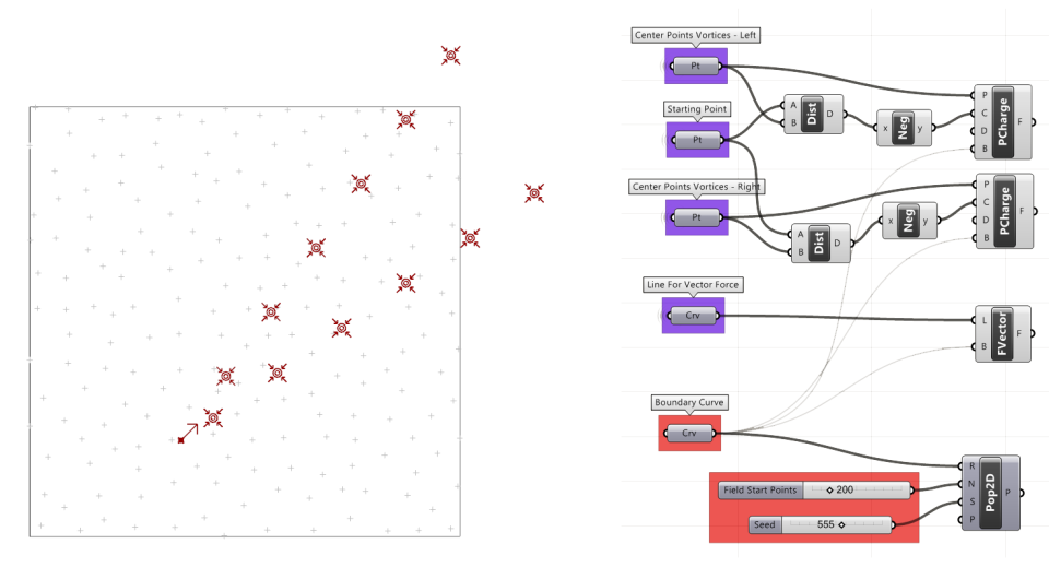
This step also introduces nothing new. I hook my vortex center points into two separate point charge generators, and use the distance from the start point to determine the strength of the negative attraction force. In other words, the further from the start, the stronger the force. This is not scientific, but seemed to give the best results for now.
I also use a small line a drew in step one to set up a Force Vector.
I attach the boundary curve into each of my forces.
In this example, I will generate my field lines using a random geometry population.
Step Three – Merging Forces with Different Data Structures
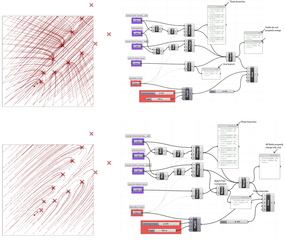
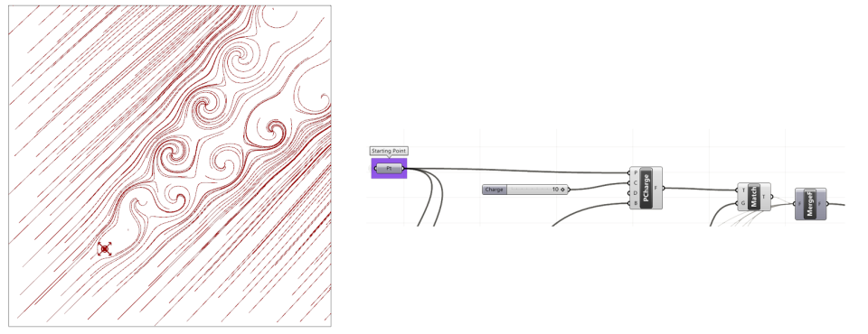
Up to this point, I have two sets of forces. Attractor “Point Charges” and the “Vector Force.” If I try to merge them, in this particular case, you may find that it will generate two separate sets of field lines. This is because in order to merge forces properly, they should all have the same data structure (our favorite topic!). You will notice in the first example, the Point Charge forces are located in the “third branch”, while the Vector Force is located in the “first branch”. This is why when I try to merge them to separate fields are generated. One way to fix this is to use the “Match Tree” component to give the Vector Force the same data structure as the Point Charges. The forces now merge properly.
Step Four – Adding Spin Forces
Now that my first two sets of forces are balanced, I will add my third set of forces, the Spin Charges. I use the distance between the force and the starting point to change the strength of these, but for the set of points on the left I use the negative values of the distances to generate a clockwise spin, while for the points on the left, I use the positive values to generate a counter-clockwise spin. Also hook up the boundary curve into the B input.
These now have to be merged with the other forces, but don’t do it yet! Save first 🙂
The more complicated your forces get, the more problems you will have with issues such as balancing and controlling them. There are also technical problems with Grasshopper you should be aware of. Often when merging forces, it will crash your computer so remember to save before plugging these in. Through experience, I have found the forces should be hooked up in a certain order, with the Vector force being hooked in last. Sometimes this isn’t a problem but this force seems to cause more problems that others. Also, if you change the boundary of one force (the B input) with other forces hooked in, this will often crash the system as well. So a few pointers.
-Plug in the Boundary Curve for each force before merging them.
-If you make a new force, it is often a good idea to disconnect all the forces, but especially the Vector Force, and then to reconnect them one by one.
-When merging forces, it is usually best to plug in the Vector Field force last.
-Make sure they all have the same data structure (see previous step).
Step Five – One More Force
This last step is simple. I decided to add a positive charge on my start point to represent the blunt object generating the Vortex Street. This is a simple, scalable charge, and it is merged with the other forces (but only after using the Match Tree Component…see step 3).
Variations
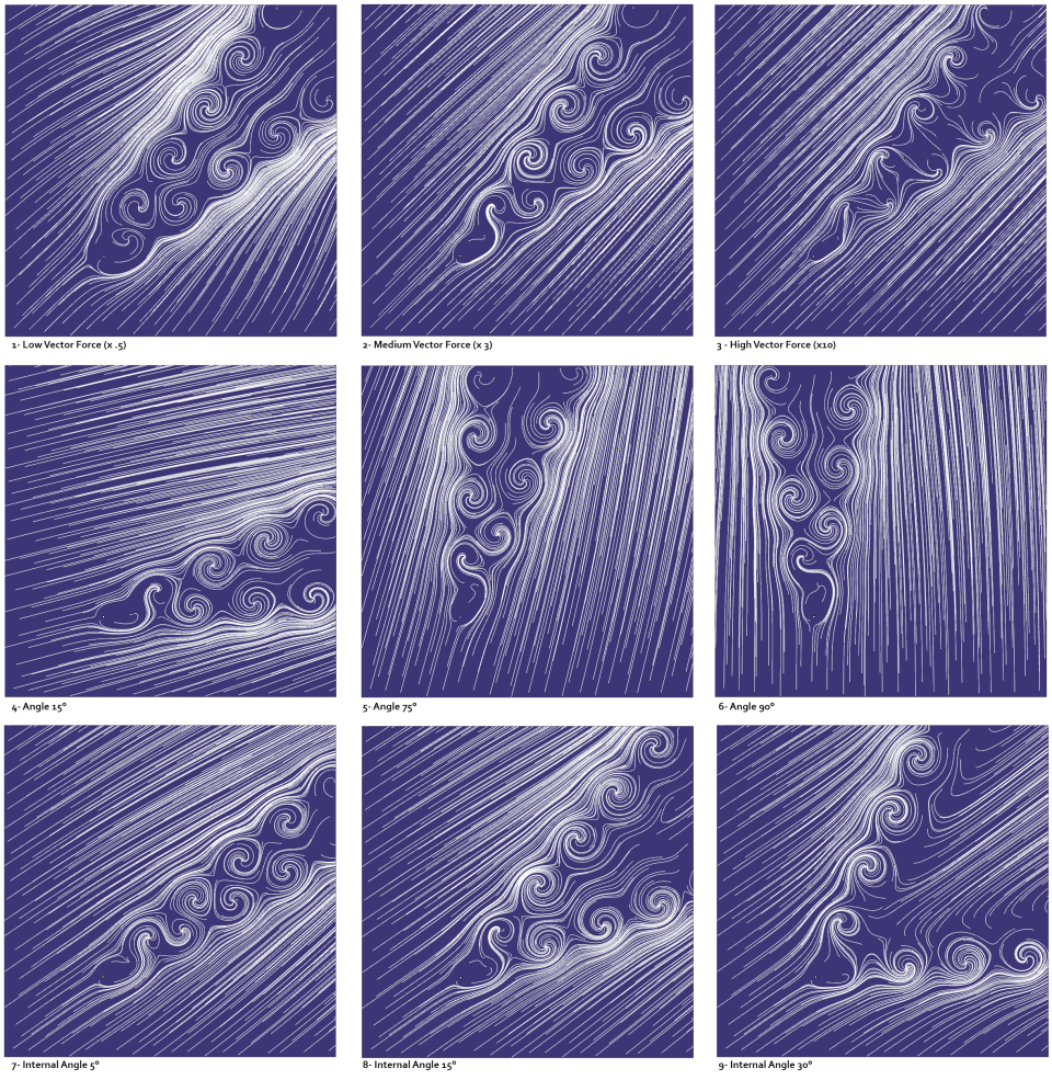
So now that it is working, you can change parameters to generate various patterns. Above are a few options. You may also want to experiment with changing the number of vortices, etc.
Like your images
LikeLike
thank you so much
LikeLiked by 1 person
This is really cool work, thank you Josclag! I sent you and email to josclag at hotmail dot com asking a few questions, is that the correct address?
LikeLike