Image Sampler – Example 2.5
I wasn’t sure where the best place to introduce the image mapper since it doesn’t go along with attractors too well, but I did it here because I wanted to do a case study of a particularly well-known Landscape Architectural project, the Keio University Noguchi Garden rooftop by Michel Desvigne in terms of the method he used to generate the form of the pavement (he used an image sampler) vs other ways it could be done, for example by using attractors. Anyway, the Image Sampler can be a fun tool to use, but using it can also be a bit tricky. I almost always have to refer back to a previous script to set it up since for me the setup isn’t that intuitive, and there is also a problem with how images are scaled to geometry that should have an easy solution, but which I haven’t yet found.
The basic logic of the image sampler is that you load an image into Grasshopper, which then analyzes the image in terms of color, pixel brightness, etc. It can then use the results of the image analysis to perform operations on geometry in Grasshopper. In these examples, I used a few different images with the same settings, clouds, wood, and a guy’s head to show how changing the image can change geometry. Then I stuck with the guy’s head to show a couple of other uses.
Image sampler can become especially useful if you are doing machine fabrication from Grasshopper / Rhino. An obvious example could be cutting out perforations on a screen based on an image. It also has potential use where you sketch a drawing, and then you use your sketches create geometry, although I haven’t done much with that yet. It’s really not parametric, although if you scan an image of complexity, such as clouds or an aerial photo, you can create the illusion of complex form.
Anyways, now on to the script…
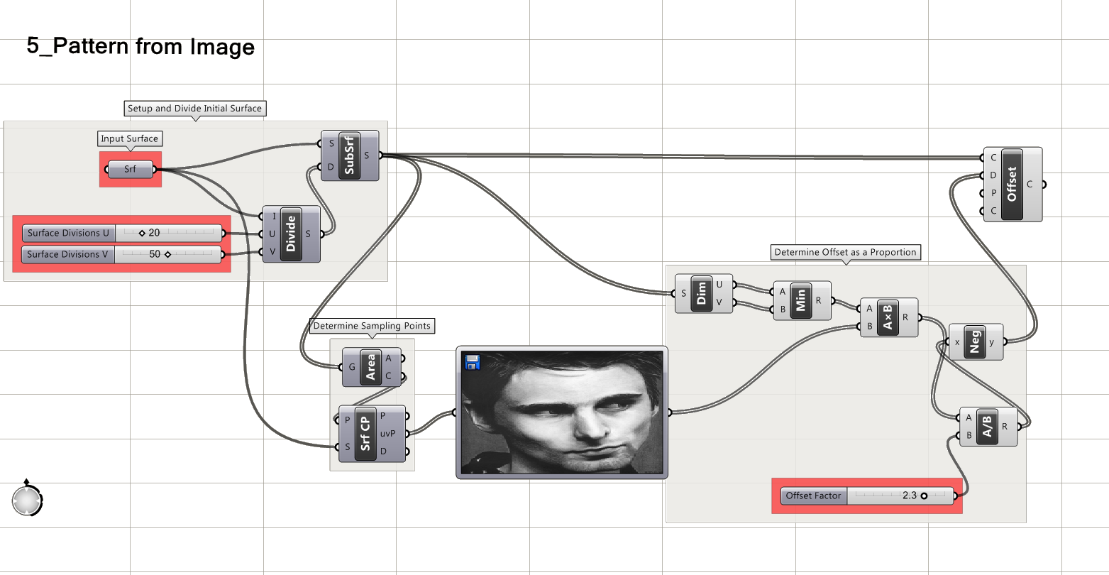
Step One – Here I subdivide a surface using Isotrim as explained in Example 2.2 and used in 2.3. I then find the center point of each sub-surface.
Step Two – You can now plop the image sampler down onto the canvas, and load your desired image. You will see several options when you open the image sampler, but in this case we are going to push the button for sampling brightness values only, not color.
Another tricky part will be adjusting the scale of what we sample, but we’ll get back to that in a minute.
Step Three – Before we tweak the scale, we are going to use a Srf CP component which takes our initial surface, takes our sampling points (the centers of the sub-surfaces) and generates an out up uvP these are the points grasshopper will test against the image to test brightness of each point. These will be used to offset the surfaces into smaller surfaces (could also use a scale component, which might be easier, but wanted to introduce offsets… there are usually multiple ways to do the same thing).
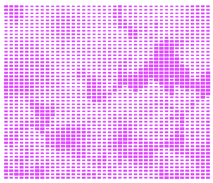
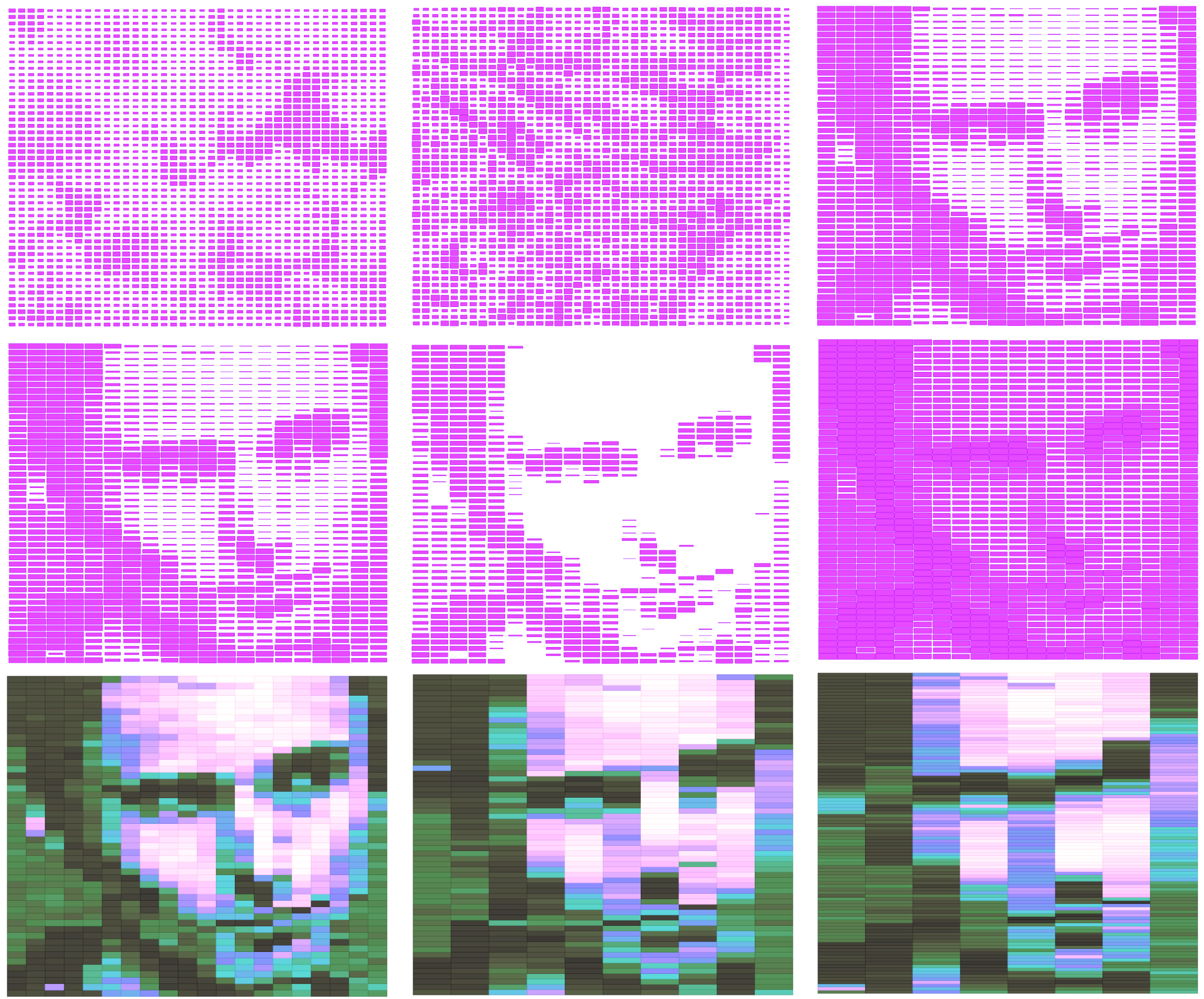
In the examples below, the images are changed in the first row, the offset factor is changed in the second, and in the third I reworked the script to use darkness values to color the pavers using one of the color commands. By adjusting the initial proportions of the surface subdivisions, the once clearly visible image can become quite abstract. This is basically just changing the pixel resolution of an image. Much more exciting stuff can be done with this, but as I said, it doesn’t create truly “parametric” form if that is what you are going for. But still handy.
Screenshot of the grasshopper definition…
I love the effect that you gained in the last row of examples by utilizing colours. Is there any chance that you could share how you achieved those gradations? The effect is ideally something I’d like to achieve at the moment and I can’t seem to figure it out
LikeLike
For the colors in the last row I used the “Colour HSL” component and simply plugged in the values generated from the image sampler into all the ports. (H + S + L) and then used this to color the geometry.
LikeLike
That’s great. Got it working perfectly. Thank you for everything.
LikeLike
I can’t get this to work. I think its because the values returning from my image sampler component that I am plugging into the multiplication port B are all returning a value of 1. So all of the surfaces are the same size. Obviously I am doing something wrong here. Im a newbie, any ideas?
LikeLike
oh never mind, I got it to work, (I had to reparameterise the original surface). Thanks for your definition :))
LikeLike
Ok! glad you got it to work!
LikeLike
newbie here too. I can’t get the image pattern to be recognized correctly. my result is pretty much like the first row, second image but it won’t develop further. I’ve tried reparameterising the surface and the offset factor, still can’t figure out where went wrong. what do you think possibly has gone wrong? thank you.
LikeLike
Hello! Can you please send a screenshot of what you connected to the HSL component?
LikeLike